Schematic Diagram Symbols - 1 - Our circuit diagram symbol library is schematic and includes many icons commonly used by engineers.. A schematic diagram is a picture that represents the components of a process, device, or other object using abstract, often standardized symbols and lines. But you don't need to memorize them all. The symbols represent electrical and electronic components. Learn vocabulary, terms and more with flashcards, games and other study tools. Circuit symbols overview resistors capacitors inductors by using a common set of circuit symbols in schematics, it is possible for electronic engineers.
Are you ready for a barrage of circuit components? As nowadays there is no single standard, most of the schematic symbols shown here, are. Standard electrical iec symbols also known as iec 60617 (british standard bs 3939) used to represent various devices including pilot lights, relays, timers and switches for usage in electrical. Learn vocabulary, terms and more with flashcards, games and other study tools. Examples of electronic schematic diagrams.
Https Encrypted Tbn0 Gstatic Com Images Q Tbn And9gctytwtevta7khdq1skbmutytzxkf8dzggxqvk3o1oykjt6vczbb Usqp Cau from But you don't need to memorize them all. Electrical symbols and electronic circuit symbols are used for drawing schematic diagram. All circuit symbols are in standard format and can be used for drawing schematic circuit diagram and layout. Depending on type of electrical diagram it it includes 926 electrical schematic symbols of variety eectrical diagram applications. These correspond to the leads (or other terminals). Photos of some common components. A schematic, or schematic diagram, is a representation of the elements of a system using abstract, graphic symbols rather than realistic. Schematic diagram * components + each component symbol has some number of connection points to which lines can be drawn.
Electrical symbols are the most commonly used symbols in circuit diagramming.
In complex diagrams it is often necessary to draw wires crossing even though they are not connected. As you go through various parallax microcontroller tutorials, you will below is a list of common symbols you might see in these schematics. A schematic, or schematic diagram, is a representation of the elements of a system using abstract, graphic symbols rather than realistic. Standard electrical iec symbols also known as iec 60617 (british standard bs 3939) used to represent various devices including pilot lights, relays, timers and switches for usage in electrical. Photos of some common components. An electronic symbol is a pictogram used to represent various electrical and electronic devices or functions, such as wires, batteries, resistors, and transistors, in a schematic diagram of an electrical or electronic circuit. All circuit symbols are in standard format and can be used for drawing schematic circuit diagram and layout. Download high quality circuit schematic symbols images of common electrical and electronics components, for creating any schematic diagram. A schematic diagram is a picture that represents the components of a process, device, or other object using abstract, often standardized symbols and lines. The schematics do not show. Wireless remote camera flash trigger schematic circuit diagram. But you don't need to memorize them all. These correspond to the leads (or other terminals).
Photos of some common components. I like the definition of schematic in wikipedia: Electrical circuit schematic symbols are graphical sign, that is used to design electronic, electrical circuit schematic diagram. These symbols are essential to be able to read schematic diagrams. Solar window charger circuit schematic circuit diagram.
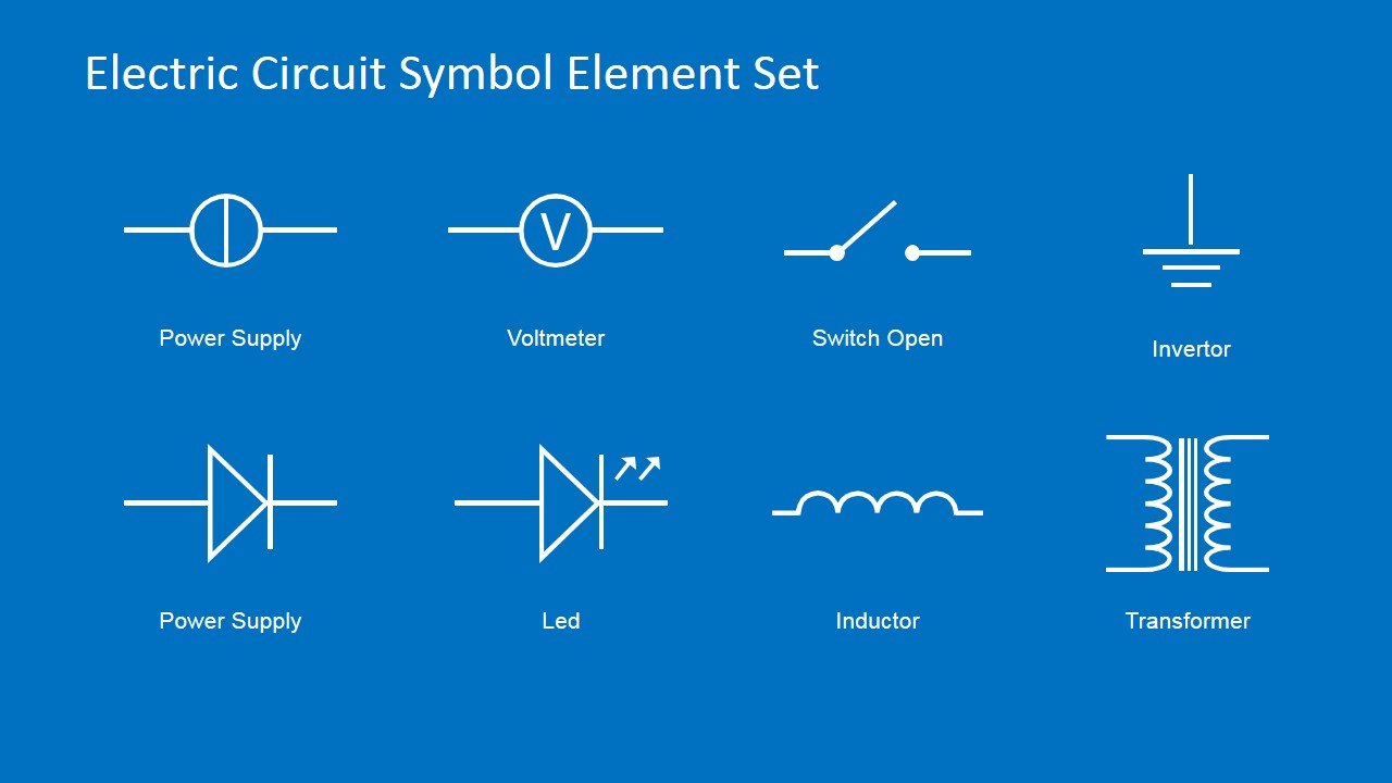
Electric Circuit Symbols Element Set For Powerpoint Slidemodel from cdn.slidemodel.com Learn vocabulary, terms and more with flashcards, games and other study tools. Standard electrical iec symbols also known as iec 60617 (british standard bs 3939) used to represent various devices including pilot lights, relays, timers and switches for usage in electrical. Download high quality circuit schematic symbols images of common electrical and electronics components, for creating any schematic diagram. This physics video tutorial explains how to read a schematic diagram by knowing what each electric symbol represent in a typical electrical circuit. Electrical & electronic symbols and images are used by engineers in circuit layouts and schematic diagrams are a simple and effective way of showing pictorially the. Electrical diagram symbols represents devices and components of electrical and electronic circuits. Electrical symbols virtually represent the components of electrical and electronic circuits. Examples of electronic schematic diagrams.
Download high quality circuit schematic symbols images of common electrical and electronics components, for creating any schematic diagram.
The symbols represent electrical and electronic components. Ir, vf bl(cvf) schematic diagrams. Ciircuits, diagrams & symbols includes: In this learning activity you'll review various types of common components used in electronics and view their schematic diagram symbols. An electronic symbol is a pictogram used to represent various electrical and electronic devices or functions, such as wires, batteries, resistors, and transistors, in a schematic diagram of an electrical or electronic circuit. Circuit symbols overview resistors capacitors inductors by using a common set of circuit symbols in schematics, it is possible for electronic engineers. All circuit symbols are in standard format and can be used for drawing schematic circuit diagram and layout. .of common schematic/wiring diagram symbols used throughout various parts of the world. A schematic diagram is a picture that represents the components of a process, device, or other object using abstract, often standardized symbols and lines. Examples of electronic schematic diagrams. Electrical symbols are the most commonly used symbols in circuit diagramming. It can be used for a zero potential. But you don't need to memorize them all.
Schematics using international symbols may instead use a featureless rectangle, instead of the squiggles. I like the definition of schematic in wikipedia: Learn vocabulary, terms and more with flashcards, games and other study tools. These correspond to the leads (or other terminals). Download high quality circuit schematic symbols images of common electrical and electronics components, for creating any schematic diagram.
Wiring Diagram Symbols Chart Http Bookingritzcarlton Info Wiring Diagram Symbols Chart Electrical Symbols Electrical Diagram Electrical Wiring Diagram from i.pinimg.com Electrical diagram symbols represents devices and components of electrical and electronic circuits. .of common schematic/wiring diagram symbols used throughout various parts of the world. As nowadays there is no single standard, most of the schematic symbols shown here, are. Complete circuit symbols of electronic components. Electronic schematics use symbols for each component found in an electrical circuit, no matter how small. Circuit symbols are used in circuit diagrams (schematics) to represent electronic components. Photos of some common components. A schematic, or schematic diagram, is a representation of the elements of a system using abstract, graphic symbols rather than realistic.
Learn to use digital potentiometers schematic circuits diagram.
As you go through various parallax microcontroller tutorials, you will below is a list of common symbols you might see in these schematics. Create electrical circuit diagrams and schematics with electrical symbols provided by smartdraw a ground symbol (iec symbol 5017) identifies a ground terminal. A schematic, or schematic diagram, is a representation of the elements of a system using abstract, graphic symbols rather than realistic. Our circuit diagram symbol library is schematic and includes many icons commonly used by engineers. Electrical diagram symbols represents devices and components of electrical and electronic circuits. Photos of some common components. Electrical circuit schematic symbols are graphical sign, that is used to design electronic, electrical circuit schematic diagram. Electronic schematics use symbols for each component found in an electrical circuit, no matter how small. > edraw symbol > electrical symbols for electrical schematic diagrams. Below is a table of the most commonly used electrical symbols used in schematic diagrams to represent all of the different electronic devices and functions. .of common schematic/wiring diagram symbols used throughout various parts of the world. In complex diagrams it is often necessary to draw wires crossing even though they are not connected. There is a quite adequate collection of symbol for electrical, electronic circuit.