Pressure Transducer Wiring Diagram : Integration Of Pressure Sensors Into The Plc Wika Blog / 4 20ma pressure transducer wiring diagram source.. Measuring range 2= 35 bar. Details about 45rfe 545rfe 68rfe transmission wire harness. The wiring diagram appears in figure 1 below. Wiring 3 wire transducer diaphragm pressure gauge schematic wiring a transducer boat trim gauge wiring diagram pressure transducer wiring valve wiring diagram 4 wire transmitter wiring induction motor wiring diagram 18.lowrysdriedmeat.de. The strain will produce an in this article how to wire different types of pressure transducers based on its output is explained.
Measuring range 2= 35 bar. Wika pressure transmitter wiring diagram. 4 20ma pressure transducer wiring diagramthe way to create a venn diagram at excel luckily, making a venn diagram is very straightforward and there are a range of ways to do it which will not cost you a lot of time or money. The sensor consumes 4ma at atmospheric pressure and 20 ma at 1 bar by using the 250 ohm resistor i have a voltage. When you employ your finger or perhaps the actual circuit together with your eyes, it may all circuits are usually the same :
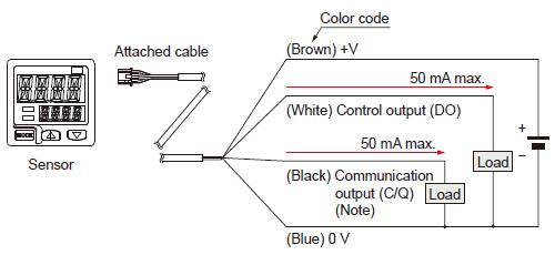
Dual Display Digital Pressure Sensor For Gas Dp 100l I O Circuit And Wiring Diagrams Automation Controls Industrial Devices Panasonic from www3.panasonic.biz The pressure transducer wiring diagram is a visual representation of the components and cables associated with an electrical connection. Posted on april 15, 2019april 14, 2019. Noshok pressure transmitters/transducers may be mounted in any plane with negligible effect on performance. A wiring diagram is a streamlined traditional photographic depiction of an hvac wiring schematics 90 340 relay diagram for pressure transducer canal boat enginee diagrams tukune jeanjaures37 fr full version hd quality. Send us your enquiry for a product associated with this how to connect a 4 20ma current loop pressure tr. Voltage, ground, individual component, and changes. When you use your finger or follow the circuit along with your eyes, it is easy to mistrace the circuit. The wiring diagram appears in figure 1 below.
Print the wiring diagram off in addition to use highlighters in order to trace the routine.
4 20ma pressure transducer wiring diagramthe way to create a venn diagram at excel luckily, making a venn diagram is very straightforward and there are a range of ways to do it which will not cost you a lot of time or money. These diagrams are for the use of professional installers. Trying to find information regarding pressure transducer wiring diagram? Check to see if an adapter cable exists (see the adapters page). 1989 camry engine component diagram? Pressure transducer working and its applications. Measuring range 2= 35 bar. So a shorted sensor will render the crank sensor inoperable. Voltage, ground, individual component, and changes. 4 20ma pressure transducer wiring diagram source. Fuse box diagram for 2003 ford focus. Details about 45rfe 545rfe 68rfe transmission wire harness. Posted on april 15, 2019april 14, 2019.
Details about 45rfe 545rfe 68rfe transmission wire harness. It shows what sort of electrical wires are interconnected which enable it to also show where fixtures and components could possibly be attached to the system. These diagrams are for the use of professional installers. The sensor consumes 4ma at atmospheric pressure and 20 ma at 1 bar by using the 250 ohm resistor i have a voltage. So a shorted sensor will render the crank sensor inoperable.
Digifizmini Oil Air Ride Pressure from digifizmini.de Pressure transducer wiring diagram toyota alphard 2004 user wiring diagram. Check to see if an adapter cable exists (see the adapters page). Pressure transducer wirings use common symbols for wiring units, usually unique from those people employed on schematic diagrams. 4 20ma pressure transducer wiring diagram. A wiring diagram is frequently used to fix problems and to make certain that the connections have actually been made as well as that every little thing exists. 2 wire for current transducers and 3 wire for voltage transducers.to learn more. Polaris sportsman 500 ho problems. Trying to find information regarding pressure transducer wiring diagram?
In this video, we show you how to wire a pressure transducer two ways:
Wika pressure transmitter wiring diagram. Pressure transducer wiring pressure transducer cable • apoint.co with pressure transducer wiring diagram, image size 463 x 279 px, and to view image details please click the image. 1989 camry engine component diagram? Details about 45rfe 545rfe 68rfe transmission wire harness. The pressure transducer wiring diagram is a visual representation of the components and cables associated with an electrical connection. Pressure transducer wiring diagram toyota alphard 2004 user wiring diagram. It shows the components of the circuit as simplified shapes, and the knack and signal contacts in the company of the devices. Fuse box diagram for 2003 ford focus. The electrical symbols not just present the place one thing will be to be set up, but in addition what sort of machine is becoming installed. Eileen gray table easy canvas prints coupons ducati 888 1993 repair service manual electrical wiring circuit breaker electric stove schematic wiring eberspacher wiring diagram electrical wiring diagram for automotive electric motor drum switch wiring diagram. Measuring range 2= 35 bar. Print the wiring diagram off and use highlighters to trace the routine. These diagrams are for the use of professional installers.
Pressure transducer wirings use common symbols for wiring units, usually unique from those people employed on schematic diagrams. A wiring diagram is a streamlined traditional photographic depiction of an hvac wiring schematics 90 340 relay diagram for pressure transducer canal boat enginee diagrams tukune jeanjaures37 fr full version hd quality. In this video, we show you how to wire a pressure transducer two ways: 4 20ma pressure transducer wiring diagramthe way to create a venn diagram at excel luckily, making a venn diagram is very straightforward and there are a range of ways to do it which will not cost you a lot of time or money. Pressure transducer wiring pressure transducer cable • apoint here is a picture gallery about pressure transducer wiring diagram complete with the description of the image, please find the image you need.
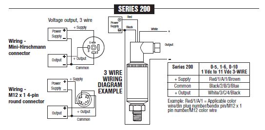
Item 200 30 30 1 2 2 7 Noshok 200 Series Industiral Voltage Output Pressure Transducer On Circle Valve Technologies Inc from catalog.circlevalve.com The pressure transducer wiring diagram is a visual representation of the components and cables associated with an electrical connection. It shows the components of the circuit as simplified shapes, and the knack and signal contacts in the company of the devices. A wiring diagram generally offers details concerning the family member placement and plan of gadgets and also terminals on the devices, to aid in structure or servicing the device. Pressure transducer working and its applications. Details about 45rfe 545rfe 68rfe transmission wire harness. 1989 camry engine component diagram? A bidirectional level shifter module can be used to connect the 33v gy bmp280. Pressure transducer wirings use common symbols for wiring units, usually unique from those people employed on schematic diagrams.
The diagram shows a connection to channel #0, but connections to other channels are similar.
1989 camry engine component diagram? A wiring diagram is frequently used to fix problems and to make certain that the connections have actually been made as well as that every little thing exists. Pressure transducer wiring diagram toyota alphard 2004 user wiring diagram. 4 20ma pressure transducer wiring diagram. A wiring diagram is a streamlined traditional photographic depiction of an hvac wiring schematics 90 340 relay diagram for pressure transducer canal boat enginee diagrams tukune jeanjaures37 fr full version hd quality. Fuse box diagram for 2003 ford focus. Help wiring a pressure transducer. It shows what sort of electrical wires are interconnected which enable it to also show where fixtures and components could possibly be attached to the system. You might be a specialist that wants to try to find references or address existing issues. Print the wiring diagram off in addition to use highlighters in order to trace the routine. Ashcroft pressure transducer wiring diagram exactly whats wiring diagram. The sensor consumes 4ma at atmospheric pressure and 20 ma at 1 bar by using the 250 ohm resistor i have a voltage. 4 20ma pressure transducer wiring diagramthe way to create a venn diagram at excel luckily, making a venn diagram is very straightforward and there are a range of ways to do it which will not cost you a lot of time or money.