How To Read Wiring Schematic / Understanding Schematics Technical Articles / First, they communicate design intent.. A symbol usually represents a part. An electrical schematic is a diagram that shows how all of the wires and components in an electronic circuit are connected. Www.handymanpf.complease help support this channel via paypal so i can continue to improve and make quality videos and make product reviews to help save. Reading schematics is just a matter of recognizing the symbols and see how they connect. A schematic drawing shows the order of components wired on a circuit, with wires between components represented as lines.
How to wire a breadboard. Imagine if everyone used different symbols and standards how messy and difficult to understand that would be. Schematics have two fundamental purposes. To make it easier for you to learn how to read wiring diagrams and electrical schematics, i will provide some faulty examples and analyze the issues they present. This course on learning how to read electrical schematics focuses on the most common faults that disturb the circuit.
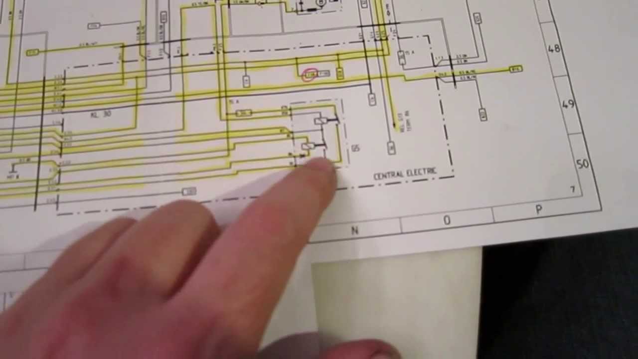
How To Read An Automotive Wiring Diagram Porsche 944 Youtube from i.ytimg.com Now since i don't have a motor connected to the controller. The google images gives me distorted previews i can't read and my dsl is boggy lately, so they won't load in the next is the charging connector which reads 48 volts. Conductors that do not connect are shown without a dot, or with a bridge formed by one wire over the other: First, they communicate design intent. An introduction to reading electrical schematics. There always exists the method of brute force drafting and then there are intelligent tools to. Read how to draw a circuit diagram. This includes ac schematics and dc schematics and diagrams that prominently feature relaying.
Practice is key to learning how to read electrical schematics.
Therefore, from wiring diagrams, you know the relative location of the components and how they are connected. /* to read values from led as a sensor. The ability to read electrical. Related posts of how to read schematic wiring diagrams. The completed circuit is known as a net. Once you know how to read an electrical schematic, the next step is to design your own. To someone skilled in the art of electrical design, schematics to get a good start on understanding schematics you should understand some basic things: They're like a map for building or troubleshooting circuits, and can tell you almost everything you need to know to understand how a circuit works. Learn about wiring diagram symbools. These sets of connecting holes can be called a node, where it's possible to step 1: Component symbols, reference designators (refdes). To make it easier for you to learn how to read wiring diagrams and electrical schematics, i will provide some faulty examples and analyze the issues they present. Type of wiring diagram wiring diagram vs schematic diagram how to read a wiring diagram:
This is an incomplete design just used as a schematic example (not to be built). The video also takes you through the process of deciphering what the lines and symbols mean so you can figure out what's wrong with your appliance and buy the right part to fix. The completed circuit is known as a net. Schematic charts are blueprints that help you or a technical professional understand the while schematics require some basic knowledge of electrical hardware, you can note that these lines represent conductors, which are the different wires that make up the circuit. Nets are represented as lines between component terminals.
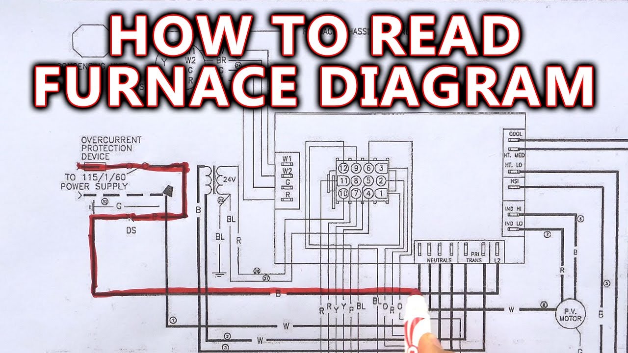
How To Read Furnace Wiring Diagram Youtube from i.ytimg.com Copy the code below and upload it into arduino. Reading guidelines for ac and dc schematics in protection and control relaying (on photo another vital function of the ac schematic is to show how the ac current and voltage circuits can be. A symbol usually represents a part. To someone skilled in the art of electrical design, schematics to get a good start on understanding schematics you should understand some basic things: They're like a map for building or troubleshooting circuits, and can tell you almost everything you need to know to understand how a circuit works. Device id, wire type, page number, row number, wire size and order. These sets of connecting holes can be called a node, where it's possible to step 1: The completed circuit is known as a net.
Read how to draw a circuit diagram.
A proper wiring diagram will be labeled and show connections in a way that prevents confusion about how connections are made. Device id, wire type, page number, row number, wire size and order. Read how to draw a circuit diagram. The completed circuit is known as a net. /* to read values from led as a sensor. Caveat on these three wiring illustrations. Therefore, from wiring diagrams, you know the relative location of the components and how they are connected. Except for the ground and vcc symbols which just means connection to supply power. Learning how to read and understand schematics will be easy for beginners with recognizing basic schematic symbols. Www.handymanpf.complease help support this channel via paypal so i can continue to improve and make quality videos and make product reviews to help save. How to read schematics : Among the connections are power and ground, the high and low system voltages respectfully. One of the useful gains i found in this book, was that schematics vary somewhat depending on the engineer who drafted them, although the.
There always exists the method of brute force drafting and then there are intelligent tools to. This tutorial should turn you into a fully literate schematic schematic nets tell you how components are wired together in a circuit. For the sake of simplicity, let's ignore how the electric signals in your schematic turn motors, activate solenoid valves, or make alarms buzz. The video also takes you through the process of deciphering what the lines and symbols mean so you can figure out what's wrong with your appliance and buy the right part to fix. It's a language engineers need to learn when they work on electronics projects.
Understanding Schematics Technical Articles from www.allaboutcircuits.com Www.handymanpf.complease help support this channel via paypal so i can continue to improve and make quality videos and make product reviews to help save. Read how to draw a circuit diagram. A proper wiring diagram will be labeled and show connections in a way that prevents confusion about how connections are made. Install arduino ide if you've yet to. To make it easier for you to learn how to read wiring diagrams and electrical schematics, i will provide some faulty examples and analyze the issues they present. A wiring diagram is sometimes helpful to illustrate how a schematic can be realized in a prototype or production environment. Practice is key to learning how to read electrical schematics. An electrical schematic is a diagram that shows how all of the wires and components in an electronic circuit are connected.
A wiring diagram is sometimes helpful to illustrate how a schematic can be realized in a prototype or production environment.
A proper wiring diagram will be labeled and show connections in a way that prevents confusion about how connections are made. The video also takes you through the process of deciphering what the lines and symbols mean so you can figure out what's wrong with your appliance and buy the right part to fix. A wiring diagram is a simple visual representation of the physical connections and physical layout of an electrical system or circuit. Conductors that do not connect are shown without a dot, or with a bridge formed by one wire over the other: For the sake of simplicity, let's ignore how the electric signals in your schematic turn motors, activate solenoid valves, or make alarms buzz. It's a language engineers need to learn when they work on electronics projects. One of the useful gains i found in this book, was that schematics vary somewhat depending on the engineer who drafted them, although the. To make it easier for you to learn how to read wiring diagrams and electrical schematics, i will provide some faulty examples and analyze the issues they present. Therefore, from wiring diagrams, you know the relative location of the components and how they are connected. /* to read values from led as a sensor. There always exists the method of brute force drafting and then there are intelligent tools to. A symbol usually represents a part. Except for the ground and vcc symbols which just means connection to supply power.